Plant operators, service contractors and engineers face the same question every Q4. “Do we have the right supplies for the shutdown season?” Shutdowns are resource and time-sensitive events, demanding proper resource and manpower planning. Valve failures during shutdowns do happen, leading to increased workloads during this slim window period.
Here is a shutdown playbook for valve distributors and customer-facing teams, providing technical, operational and risk-based guidance for inspecting and preparing valves for the Q4 maintenance season. Whether you are supplying ball, steam, solenoid, check and automated valves, Y-strainers, or anything in between, this checklist helps you identify and address customers’ shutdown needs.
Why Distributors must be Ready for the High-Risk Q4 Shutdown Maintenance Season

In Q4, most industrial plants experience:
- Peak production stress, which pushes systems to the maximum
- Increased leak risks in ageing valves
- Deposits in Y-strainers
- Frequent actuator failures emanating from worn-out seals and motor fatigue for actuated valves
- Fatigue failures in steam, condensate, liquid and air systems
- Solenoid valve failures occur as coils approach the end of life.
During shutdowns, each minute counts and customers expect distributors to respond accordingly. Customers expect distributors to:
- Provide like-for-like valve replacements.
- Offer exact Cv and orifice matching.
- Guarantee limited-time actuator swaps (preferably a day or a few days).
- Facilitate quick procurement for obsolete product models.
- Verify valve pressure and temperature compatibility.
Atlantic Valves is your dependable valve supplier, ensuring you can stock and deliver exactly what customers want for their Q4 shutdown season, accurately and faster.
Q4 Valve Maintenance Symptoms You Should Not Ignore
What are some of the warning signs that maintenance teams must be aware of? And why is understanding these signs critical for preventing unprecedented failures and valve outages, even after the shutdown season is over.
Case 1: A 1” stainless steel steam solenoid valve has a weeping sound with slight leakage
A solenoid steam valve approaching failure exhibits the following signs:
- A slight hissing noise from the valve.
- Rust streaks (brown) around the valve body. More visible for carbon steel valves.
- Condensation dripping from the solenoid bonnet.
- White steam plume around the valve.
- Solenoid coils operate at noticeably elevated temperatures compared to surrounding equipment.
Such symptoms are likely caused by:
- Seat erosion caused by flashing or wire-drawing, particularly in high-pressure steam applications with frequent cycling.
- Thermal fatigue resulting from repeated heating and cooling cycles during startup and shutdown events.
- The coil is overheating due to continuous duty and poor ventilation.
- Seal degradation due to prolonged exposure to elevated temperatures and condensate
Shutdown risks: Minor steam leakage during normal operation can rapidly escalate during shutdown conditions. As system pressures and temperatures fluctuate, partially eroded seats and fatigued seals may fail completely, resulting in:
- Uncontrolled steam release
- Increased burn and safety hazards
- Energy losses
- Extended shutdown durations due to unplanned valve replacement
Distributor tip: Stock high-temperature solenoid repair kits and fast-moving, commonly ordered steam solenoid valves.
Case 2: Slow actuation/sticking of 2″ Stainless Electric Ball Valve
Electric ball valves approaching functional degradation often exhibit progressive increase in actuation resistance rather than sudden failure. These early indicators should be treated as warnings of declining torque margin and actuator reliability.
Observed Field Symptoms
Typical characteristics observed during operation include:
- Valve actuation time exceeds the normal baseline, often by more than 1.5x the specified actuation time.
- Actuator strain or hesitation as the valve approaches the fully open or fully closed position
- Overload protection systems experience regular tripping.
- Inconsistent valve positioning or incomplete end-of-travel confirmation.
Likely causes for these symptoms are:
- Failing or misaligned limit switches, resulting in improper travel feedback or premature cut-off
- Increased breakaway torque caused by buildup of viscous or sticky process media on the ball and seat surfaces
- Seat material degradation or heat fatigue, increasing friction at elevated operating temperatures
- Actuator wear or ageing, reducing available output torque relative to original design margins
Shutdown risk: inability to isolate piping sections. This leads to delays in shutdown sequencing.
Distributor tip: Electric ball valves exhibiting delayed or inconsistent actuation should be evaluated for actuator replacement or valve refurbishment during the shutdown window. Distributors should ensure availability of:
- Commonly specified electric actuators with compatible mounting patterns and torque ratings
- Pre-assembled or bolt-and-go actuator replacements to minimize installation time
- Technical support to verify torque requirements and end-of-travel settings prior to commissioning.
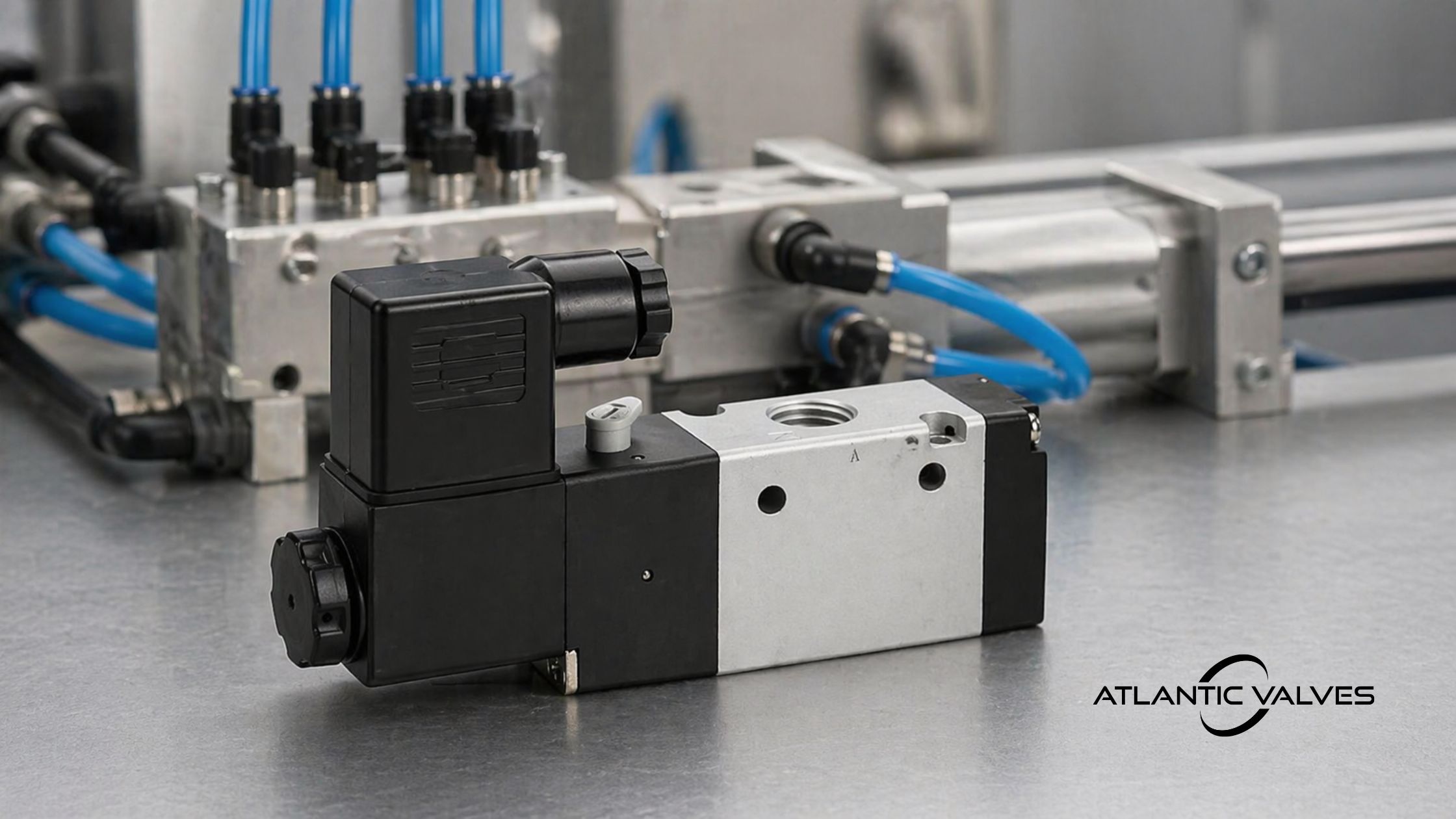
Case 3: 1/4” 3-Way 24V DC Electric Solenoid Valve is overheating
Solenoid valve overheating is a critical reliability warning. When left unaddressed, elevated coil temperatures accelerate insulation breakdown and can lead to sudden valve failure during operation or shutdown.
Observed Field Symptoms
When a solenoid valve is overheating, maintenance teams may physically observe or experience the following:
- A burnt or acrid odor originating from the solenoid valve
- Valve feels hotter than adjacent piping and equipment.
- Humming or buzzing sound.
- Progressive discoloration of the solenoid coil or outer casing, turning brownish or black.
These signs are caused by:
- Continuous solenoid valve cycling in high-temperature environments, resulting in cumulative heat build up beyond the coil’s thermal class rating
- Increased magnetic resistance due to the presence of debris in the plunger tube, which reduces magnetic efficiency and increases current draw.
- Incorrect voltage (e.g. using 24V DC for a 24V AC solenoid), leading to excessive heating due to improper impedance and magnetic field behavior.
Shutdown risk: Unexpected valve closure, which causes process interruptions or pressure surges.
Distributor tip: Solenoid valves exhibiting overheating symptoms should be flagged for immediate evaluation or replacement during the shutdown window. Distributors should ensure the availability of:
- High temperature rated solenoid valves suitable for the application
- Correctly rated (AC/DC) coils with verified voltage and duty cycle specifications
- Technical support to confirm electrical compatibility and operating conditions prior to reinstallation.
Case 4: Backflow in pipelines
Swing check valves and vertical (spring-loaded) check valves may undergo failure, following an extended period without maintenance or replacement of damaged units. When check valves fail, the disc/flapper delays or does not return back to its seat. As a result, backflow occurs, affecting normal operations and maintenance interventions, including shutdown interventions.
Observed Field Symptoms
The following are physical symptoms and system fluctuations associated with damaged swing and vertical check valves that inspection teams will observe.
- Pressure swings downstream during flow changes.
- Reverse fluid flow that is detectable by flow gauges. Reversed fluid flow indicates that the valve has lost its sealing integrity at the disc-seat interface.
- Increased instances of water hammer.
- Chattering or rattling noises in pipelines, especially when fluid flow through the system keeps fluctuating.
Likely causes of these symptoms are:
- Debris, including particulates, scale and corrosion products, is getting stuck in the check valve seats. The presence of debris prevents full seating contact and causes leaks at the sealing interface, resulting in pressure swings downstream. It also results in delayed valve closure, increasing the risk of water hammer.
- Worn-out seat due to media erosion, making the disc not seat properly and lowering the sealing integrity of the check valve, thus increasing valve susceptibility to chattering and vibrations.
- Worn-out return spring, leading to non-return of vertical (spring-loaded) check valves and permitting reverse flow of fluids.
Shutdown risk: Worn out check valve seats allow media backflow and create unintended contamination pathways. Unintended contamination may force full-line isolation and cleaning after shutdowns before production starts. Back pressure and pressure-transient events due to poor sealing transmit mechanical stress to downstream equipment and pumps and can cause unforeseen equipment damage, extending downtime and the anticipated duration of shutdown activities.
Distributor tip: Check valves exhibiting signs of failure should be lined up for replacement during shutdowns. These valves should be replaced with the exact type and size (with matching pressure and temperature rating) for quick turnaround. As a distributor, focus on stocking common sizes of industrial swing and vertical check valves to ensure they are readily available for time-critical shutdowns.
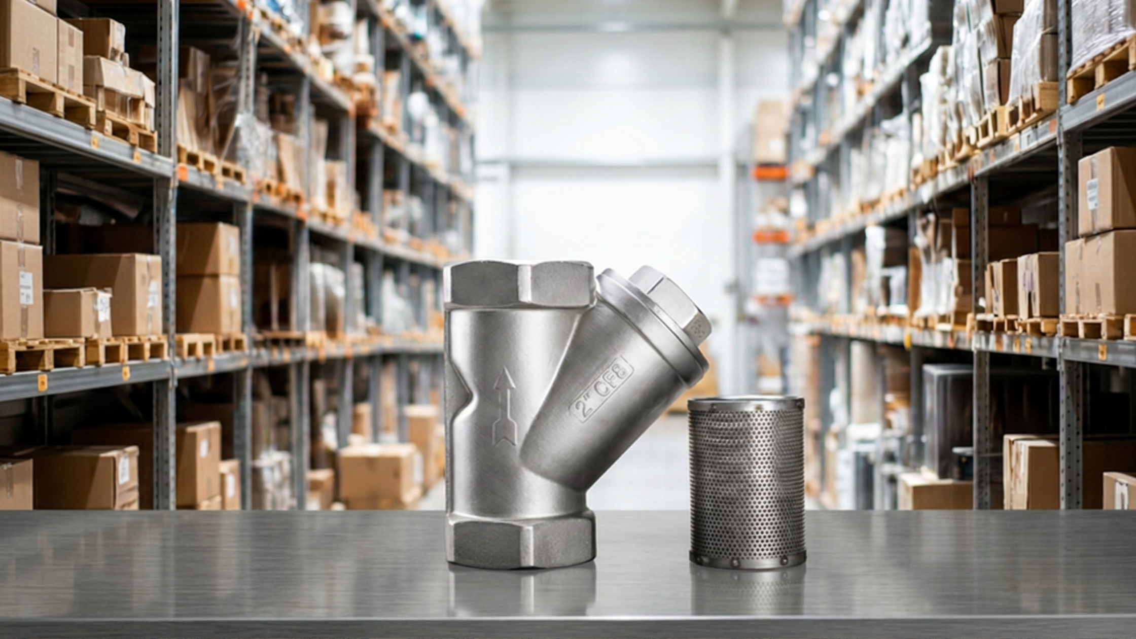
Case 5: Y-strainer malfunction
Y-strainers are installed to remove particles, contaminants, scales and rust flakes before fluids enter sensitive downstream equipment and piping systems. A clogged or malfunctioning Y-strainer becomes a silent failure point once it loses its protective capacity. Failing to inspect and service Y-strainers during the shutdown season can compromise restart success.
Observed Field Symptoms
Pre-shutdown inspections can unearth several signs of Y-strainer failures and associated system malfunctions. Here are some symptoms of a failed or failing Y-strainer:
- Increased pressure drop readings across the Y-strainer, which can be up to 10-30%. This causes cavitation in high-temperature sections of the pipeline.
- Notable pipe vibration which is likely caused by turbulence.
- Visible debris deposits in the Y-strainer blowdown.
- Flow restriction or low flow at equipment. Starved fluid flow lowers system efficiencies and can result in flow imbalances in branched piping systems.
- Externally visible leakage at the Y-strainer cover or gasket.
These signs are caused by:
- Accumulation of debris, which includes particles, scales, rust flakes, pitted metals and seal fragments, which clog the Y-strainer mesh and restrict flow capacity, resulting in increased pressure drop across the Y-strainer. Restricted flow capacity forces pumps to work harder than usual to maintain flow rates.
Shutdown risk: Damaged Y-strainers lose their filtration capabilities, causing unfiltered fluid containing heavy debris to flow downstream. Unfiltered fluids with debris exposes downstream equipment, valves and regulators to accelerated wear and tear, which ultimately leads to damage.
Distributor tip: Stock Y-strainer replacement kits and pre-sized Y-strainers to ensure customers have access to necessary supplies within the shortest time. It ensures faster restoration of filtration systems and timely restart of fluid systems.
Step-by-step Q4 Valve Maintenance Checklist
Step 1: Pre-shutdown inventory check
Activities in this step require the input of the customer and valve distributor. There are several things that the involved parties must check and verify before proceeding with the shutdown. The pre-shutdown inventory check is necessary for reducing specification uncertainties and avoiding procurement delays before the shutdown window begins. Here is a list of things you must check and their relevance to shutdown planning and execution.
| What to check | Relevance | Tools to use |
| Valve sizes, pressure rating and end connections (verify data against nameplate data or manufacturer datasheets) | To prevent delays due to product mismatches and avoid incorrect product substitutions | Measurement tools like calipers and inspection forms |
| Media types | To check and verify compatibility with valve body, seat and seal materials | Use material safety data sheets (MSDS) |
| List of all installed valve models and identification numbers | To ensure correct replacements, better valve/part traceability and accurate like-for-like part replacement | Piping and instrumentation diagrams (P&ID) and previous invoices |
| Actuator torque specifications | To ensure automated valves are correctly fitted and verify there is sufficient margin for breakaway torque and end-of-travel sealing | Manufacturer’s torque charts |
| Electrical/Air supply for automated valves | For correct coil and actuator matching | Multimeters, pressure gauges |
Valve distributors can improve their competitiveness by providing valve matching services to customers in collaboration with Atlantic Valves’ technical teams.
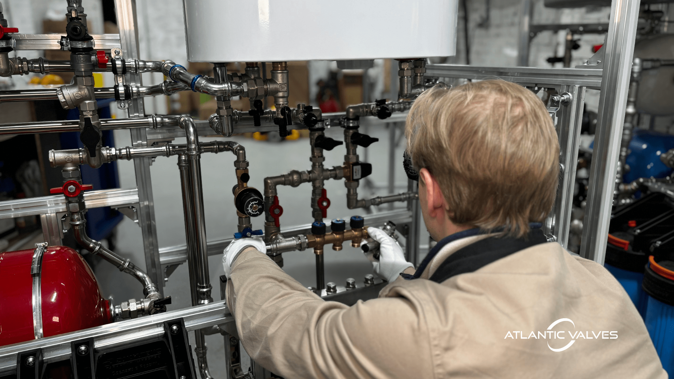
Step 2: Physical inspection
The customer conducts a plantwide walkdown. The walkdown at this stage is to identify valves requiring further evaluation. There is no detailed valve diagnosis or repair at this point. During the walkdown, check the following things:
- Leaks around the valve body and end connections. Take note of all leakages from the valves, whether they are active or residues from past leaks.
- Discolouration on the solenoid coils
- Steam stains and rust on valves
- Burning smell around solenoid valves and electrically-actuated ball valves
- Air leaks on pneumatic actuators
- Noises near check valves
- Delayed valve actuation or incomplete valve travel. Remember actuation delays are relative to baseline performance limits and normal operating behaviors.
- Physical signs of pitting or corrosion
- Mislabelled or corroded valve tags. Missing or unreadable valve tags affect traceability during shutdown replacements and can result in product mismatches or incorrect installations.
Valves with any of the above signs should be marked for replacement.
Step 3: Pre-shutdown functional testing
Customers should check if all valves in service are working properly. Functional checks for each valve type vary. Some checks that distributors need to advise customers to conduct are:
For solenoid valves
- Test coil resistance.
- Verify if the valve is connected to the right electrical supply.
- Inspect the plunger for sticking and travel distance.
Actuated valves
- Measure the actuator response time and compare it with the manufacturer’s specification.
- Confirm if the torque is sufficient.
- Operate the valve at fully open and fully closed positions and check if fluid flow characteristics are as required.
- Check if actuator limit switches are in good working condition.
Check valves
- Listen for chatter and monitor system pressure characteristics.
- Inspect valve seats for scratches or deformities.
- Check for backflow in the system.
Y-strainers
- Check mesh integrity.
- Inspect screening mesh for scale and particulate accumulation.
- Perform blowdown (for strainers with blowdown).
Step 4: Shutdown replacement and repair
The next step involves replacing and repairing damaged valves. This stage requires combined efforts from the distributor and the customer since every decision at this stage directly affects shutdown duration, safety exposure and restart success. For seamless operations, the customer should rely on the findings from Step 2 (Physical Inspection) and Step 3 (Functional Testing) to prioritize repair and replacement of valves exhibiting signs of failure. Additionally, the decision to repair or replace a valve should not be based on visible damage only. Maintenance teams must evaluate the criticality of each valve before making the final decision. Some of the valves that should be considered for immediate replacement during shutdown are those with the following signs:
- Leaking valves
- Solenoid valves with discoloured bodies
- Valves with eroded seats
- Check valves in systems that have backflow and recurrent water hammer
- Valves whose actuators stick
Customers create a detailed bill of materials (BOM) that contains a list of all:
- New valves with the same size, Cv, pressure class, temperature rating, material compatibility and end connection type as the damaged one
- Solenoid coils along with their voltage type (AC/DC), insulation class and duty cycle, which should match the specification of the original valve.
- Valve repair kits
- Actuator repair kits
- Gaskets and fasteners
- Filters and repair kits for Y-strainers
BOM from the customer should be finalized and validated before the shutdown execution phase to avoid last minute substitutions and procurement delays. Early BOM validation also gives distributors ample time to plan logistics and avail the correct replacement products.
Step 5: Post-repair and replacement validation
After installing replacement units, the customer must conduct thorough validation. They must ensure that installed valves and parts meet the requirements of the fluid application and operate as required. The validation process can be completed with the help of the distributor’s technical team.
Tip: Document everything during the shutdown. List what parts have been replaced and the performance characteristics of each valve before release for full service. You can always utilize shutdown documentation as a reference for future valve repairs and replacements.
To Fix or to Replace?
Here is a simple matrix that engineers and decision-makers can use to identify whether they should replace valves or not.
|
Symptom |
Fix |
Replace |
| Steam leak with rust streaks | Replace | |
| Solenoid valve discoloration | Replace | |
| Sluggish actuator | Lubricate/check air or electrical supply (Replace if sluggish behavior persists after basic corrective measures are implemented) | |
| Backflow | Replace | |
| Clogged Y-strainer | Clean/ replace screening mesh | |
| Mild leakage around solenoid | Fix (seal kit) | |
| Actuator not reaching 100% travel | Replace (actuator) |
Why Atlantic Valves’ Like-for-Like Matching is Essential During Q4 Shutdown
Atlantic Valves like-for-like matching is an effective risk-mitigation and specification control solution to customers walking into the Q4 shutdown season with various uncertainties. These uncertainties arise from poor or incomplete record-keeping, undocumented valve modifications and obsolescence. Due to such uncertainties, customers may enter the shutdown season having little or no information about valve specifications, like:
- Exact valve model required
- Pressure and temperature ratings
- Cv and orifice sizes
- Body material requirements
- Coil voltages and actuator torque
Atlantic Valves and their distributors offer like-for-like matching services to customers during the Q4 shutdown period. The like-for-like matching service helps customers to:
- Minimize downtime and ensure plants are back to service within the shortest time.
- Reduce installation errors
- Prevent oversizing or undersizing process valves.
- Ensure compliance with engineering and safety codes.
- Establish and win customer trust, and repeat business.
Final Words
Q4 shutdown season comes with a fair share of challenges. Plant engineers, technicians, decision-makers and distributors must prepare early to avoid pitfalls associated with high-intensity work under tight schedules. Q4 shutdown is incomplete if valve inspection, repair and replacement is unaccounted. Develop a detailed valve maintenance plan and include it in the Q4 shutdown program to minimize shutdown. Liaise with Atlantic Valves’ technical teams and distributors if you need help with like-for-like matching when looking for replacement valves and repair kits.