The pneumatic system is one of the most widely used methods of motion control. Compressed air is safe, readily available, and relatively easy to control compared to hydraulic or electric actuation in many applications. Within these systems are various control devices that are necessary to keep the system in operation.
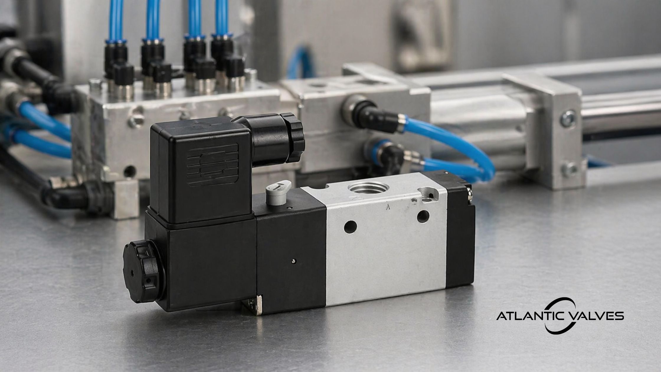
One of these control components is the solenoid valve. Industrial pneumatic solenoid valves control the flow of compressed air through automated electrical signals. They serve as the interface between electronic control systems—such as PLCs—and mechanical pneumatic devices like cylinders, actuators, and air-driven tools.
The Role of Pneumatic Solenoid Valves in Automation Systems
Pneumatic solenoid valves play a critical role in automation systems by enabling precise, repeatable control of air-driven motion. Beyond simple actuation, they define how and when air is directed within a circuit, directly influencing cycle timing, sequencing, and overall system efficiency.
In automated processes, these valves are used to manage functions such as start/stop control, directional switching, and fail-safe positioning during power loss. Their fast response time and compatibility with PLC-based control systems make them essential for high-speed and synchronized operations.
By determining airflow paths and response behavior, solenoid valves ultimately impact system reliability, energy consumption, and production consistency.
Common industrial applications include:
| Industry | Typical Use |
| Manufacturing | Automated assembly systems |
| Packaging | Filling machines, sorters, sealers |
| Automotive | Robotic fixtures and positioning clamps |
| Food Processing | Filling and handling systems / Pneumatic actuators in washdown equipment |
| Water Treatment | Air-operated valve control |
| Electronics Manufacturing | Precision pneumatic control |
Many production lines run hundreds of pneumatic actuators simultaneously. Each actuator often relies on a solenoid valve to control motion.
Operating Principle of a Pneumatic Solenoid Valve
At the core of every pneumatic solenoid valve is a simple but highly effective principle: converting an electrical signal into controlled airflow. This allows automated systems to precisely direct compressed air to where and when it is needed.
When an electrical current is applied to the solenoid coil, it generates a magnetic field that actuates an internal moving element—either a plunger or a spool, depending on the valve design. This movement shifts the internal sealing surfaces and opens or closes specific air passages inside the valve body.
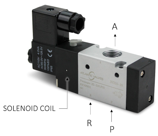
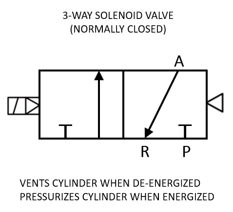
In practical terms, this switching action determines how compressed air flows between the valve’s ports. For example, in a typical 3/2 valve, energizing the coil connects the supply port (P) to the outlet (A), allowing air to flow to an actuator. When the coil is de-energized, the valve returns to its default state—usually via a spring or air return mechanism—redirecting the outlet (A) to the exhaust port (R) to release pressure.
More complex configurations, such as 5/2 valves, follow the same principle but control multiple flow paths simultaneously. Instead of simply supplying or exhausting air, they alternate airflow between two actuator ports, enabling bidirectional motion in double-acting cylinders.
Despite differences in configuration, the underlying operation remains consistent across most pneumatic solenoid valves:
- Energized state: Electrical input shifts the internal element, opening specific flow paths
- De-energized state: A return mechanism restores the default position
- Airflow control: Internal porting defines whether air is supplied, blocked, or exhausted
This electromechanical process happens very quickly—often within milliseconds—making solenoid valves ideal for high-speed and repeatable automation tasks. Their responsiveness, combined with clearly defined flow paths, allows precise control over actuator timing, sequencing, and overall system behavior.
Types of Pneumatic Solenoid Valves
Pneumatic solenoid valves are usually described by how many airflow ports they have and how many switching positions exist.
The most common categories are 2-way, 3-way, and 5-way valves.
| Valve Configuration | Function | Typical Application |
| 3/2 valve | Diverts air between two paths | Single-acting cylinders |
| 5/2 valve | Controls two airflow directions | Double-acting cylinders |
| 5/3 valve | Provides three positions | Advanced cylinder control, mid-position holding |
In automated equipment, 5/2 directional valves are probably the most common because they control both extension and retraction of cylinders.
Single Solenoid vs Double Solenoid Valves
One of the most important distinctions in directional control valves is the method of actuation: single solenoid (spring return) versus double solenoid (detent/memory). This characteristic determines how the valve behaves during power loss and how it interacts with the overall control system.
Single Solenoid (Spring Return)
A single solenoid valve uses one coil to actuate the valve and a mechanical spring to return it to its default position when de-energized.
- Fail-safe operation: Automatically returns to a predefined safe state when power is lost
- Common configurations: 3/2 and 5/2 valves
- Typical applications: Systems where safety is critical, such as emergency shutdowns or air supply isolation
Because of this behavior, single solenoid valves are widely used in applications where the system must revert to a known condition during faults or power interruptions.
Double Solenoid (Detent / Memory)
A double solenoid valve uses two coils—one for each switching position. Once actuated, the valve remains in its last position even after power is removed.
- Memory function: Holds the last state without continuous power
- No spring return: Position is maintained until the opposite coil is energized
- Common configurations: Typically 5/2 or 5/3 valves
- Typical applications: Situations where actuator position must be maintained, such as clamping, indexing, or sequencing operations
This type of valve is useful for energy efficiency and maintaining system states, but it requires careful design consideration since it does not automatically return to a safe position.
Direct Acting vs Pilot Operated Valves
While solenoid configuration defines how a valve behaves electrically and logically, another key distinction is how the valve operates mechanically—either through direct electromagnetic force or with the assistance of system pressure. This determines the valve’s capability in terms of flow capacity, pressure requirements, and energy consumption.
Direct Acting Valves
Direct-acting valves use the electromagnetic coil alone to push or pull the plunger. The valve does not rely on system pressure to operate. Even at very low pressure, the valve can still open or close.
The downside is limited flow capacity. The solenoid can only generate a certain amount of force, so these valves are usually smaller.
They are often used in instrumentation systems or smaller pneumatic circuits.
Pilot Operated Valves
Pilot-operated valves operate by using system air pressure to assist the valve switching process. The solenoid coil only needs to move a tiny pilot mechanism, and the system’s own pressure does the heavy lifting. This allows pilot-operated valves to handle much larger flow volumes with a smaller, less power-hungry coil.
This design allows relatively small coils to control larger flow capacities. However, one key limitation is the requirement for a minimum differential pressure (ΔP) between the inlet and outlet. If the system pressure is insufficient to meet this minimum ΔP requirement, the valve will not shift properly. As a result, pilot-operated valves may not function reliably in low-pressure or zero-pressure conditions.
Because of this operating characteristic, pilot-operated valves are typically used in larger pneumatic systems where stable and adequate pressure is available, making them well-suited for industrial automation applications.
Key Specifications That Should Be Evaluated
When selecting solenoid valves, several specifications tend to come up quickly.
Operating Pressure Range
Each valve is designed to operate within a pressure range.
Direct-acting valves often operate from 0 bar differential pressure, while pilot-operated designs may require a minimum pressure to shift properly. Operating outside the recommended range can cause erratic switching or internal leakage.
Flow Coefficient (Cv)
Another important parameter is flow capacity, commonly expressed as Cv. This value indicates how much air the valve can pass through it.
Undersized valves restrict airflow and slow actuator response. Oversized valves generally work fine but increase system cost and space requirements.
Coil Voltage and Electrical Characteristics
Industrial solenoid valves typically come in several coil voltage options.
Common values include:
- 24 VDC
- 24 VAC
- 110-120 VAC
- 220–240 VAC
In most modern automation systems, 24 VDC coils are preferred because they integrate easily with PLC outputs and industrial control systems.
Low power consumption is also beneficial when large valve manifolds are used.
Response Time
In high-speed automation systems, response time can matter. Fast switching allows more precise control of pneumatic motion and helps synchronize actuators with machine operations.
In packaging or assembly equipment, small timing differences can sometimes affect cycle performance.
Port Configuration and Standard Labeling
Equally important—but often overlooked—is the standard port designation used in directional control valves. Understanding these conventions ensures correct piping, prevents misconnection, and simplifies troubleshooting.
Typical labeling follows industry standards:
- Port 1 – Pressure supply (P)
- Ports 2 & 4 – Working/output ports (A & B)
- Ports 3 & 5 – Exhaust ports (R & S)
These designations are consistent across most pneumatic directional valves (e.g., 3/2, 5/2, 5/3), regardless of manufacturer. Misinterpreting port functions can lead to improper actuator movement or system malfunction, making this a critical specification to verify alongside mechanical and electrical parameters.
Example:
5/2 Valve Port Labeling
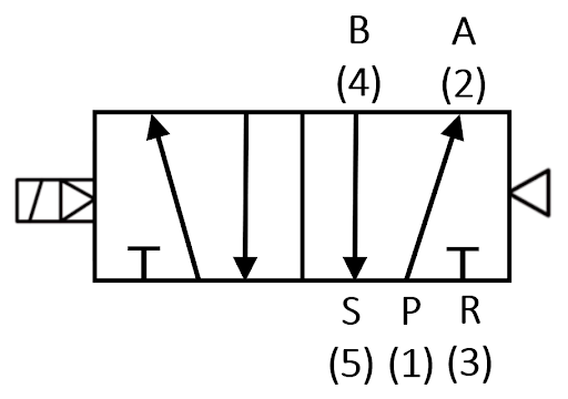
1 (P) – Air supply
2 (A) – Output port A
4 (B) – Output port B
3 (R) – Exhaust for A
5 (S) – Exhaust for B
Environmental Protection
Industrial environments are rarely clean. Dust, oil mist, moisture, and vibration can affect valve reliability.
This is why many industrial solenoid valves are rated according to IP (Ingress Protection) classifications defined by IEC 60529.
Common ratings include:
| IP Rating | Protection Level |
| IP65 | Dust-tight and protected from water jets |
| IP67 | Dust-tight and protected from temporary immersion |
In wash-down environments, stainless steel components or sealed coil housings may be required.
Relevant Industry Standards
Several standards influence the design and application of pneumatic solenoid valves.
While not every installation requires strict compliance, these standards provide useful guidance.
ISO 5599 defines interface dimensions for pneumatic valve manifolds. This allows valves from different manufacturers to fit standardized mounting systems.
ISO 12238 specifies standardized mounting interfaces and porting arrangements for pneumatic directional control valves, particularly for sub-base mounted configurations. This ensures interchangeability and consistency in valve installation across different systems and manufacturers.
ISO 4414 provides general safety and design guidelines for pneumatic fluid power systems.
Electrical protection levels are typically defined under IEC 60529, which specifies ingress protection ratings.
In hazardous areas where flammable gases or dust may be present, valves may require certification under ATEX or IECEx standards. These certifications ensure the electrical components cannot ignite surrounding atmospheres.
These references provide a useful foundation when designing pneumatic circuits or evaluating valve performance.
OEM Considerations When Selecting Solenoid Valves
For OEMs, solenoid valves are integrated components within the machine design, and several factors influence the selection process.
System Integration
Manufacturers often install solenoid valves in grouped assemblies or centralized valve stations. These systems distribute compressed air to multiple actuators from a single location. By doing so, they reduce tubing complexity and simplify machine assembly.
Space Constraints
Equipment designers use compact solenoid valve configurations to save valuable space. These designs reduce the footprint of control panels and pneumatic cabinets, making them ideal for machines with limited enclosure space. As a result, designers can create more efficient and organized system layouts.
Reliability
Engineers consider reliability a key factor when selecting a solenoid valve. A single valve failure can stop an entire machine or production line. Therefore, OEMs and industrial users choose suppliers that deliver proven designs, consistent manufacturing quality, and dependable performance.
Manufacturers also evaluate cycle life when designing equipment and selecting components. Under proper operating conditions, some industrial solenoid valves can perform tens of millions of switching cycles. This extended service life reduces maintenance requirements, minimizes downtime, and improves overall system reliability.
Distributor Supply Considerations
Industrial distributors face a slightly different challenge. Instead of designing machines, they must supply components that support many different customer applications. Because of this, distributors typically stock a range of commonly used valves.
Examples include:
- 3/2 solenoid valves
- 5/2 directional valves
- Pneumatic valve manifolds
- Replacement coils
- Seal kits and repair components
- Common port sizes include 1/8″, 1/4″, and 1/2″ NPT or BSP threads.
Stocking reliable products is critical. Low-cost valves that fail frequently can create long-term problems for distributors because customers expect consistent performance. Many distributors, therefore, work with manufacturers that maintain consistent quality control and traceability.
Providing technical support also adds value. Customers often need assistance identifying the correct valve configuration for their pneumatic systems.
Final Thoughts
Industrial pneumatic solenoid valves play a critical role in automated machinery and pneumatic control systems.
For OEMs, proper valve selection affects actuator performance, machine reliability, and serviceability. Factors such as flow capacity, electrical compatibility, environmental protection, and manifold integration all influence how well a valve performs in the long term.
For industrial distributors, maintaining a reliable inventory of commonly used valves helps support a wide range of customer applications across manufacturing, packaging, and process industries.
Standards such as ISO 5599, ISO 4414, and IEC 60529 provide useful reference points for ensuring compatibility, safety, and consistent performance.
Selecting the right pneumatic solenoid valve involves balancing technical requirements with reliability and availability. When properly specified, selected, and maintained, these devices provide the precise and dependable control that modern industrial automation depends on.
Need help sourcing pneumatic solenoid valves for OEM builds or distributor inventory? Atlantic Valves supplies reliable valve options backed by product support, fast response, and availability for industrial applications.