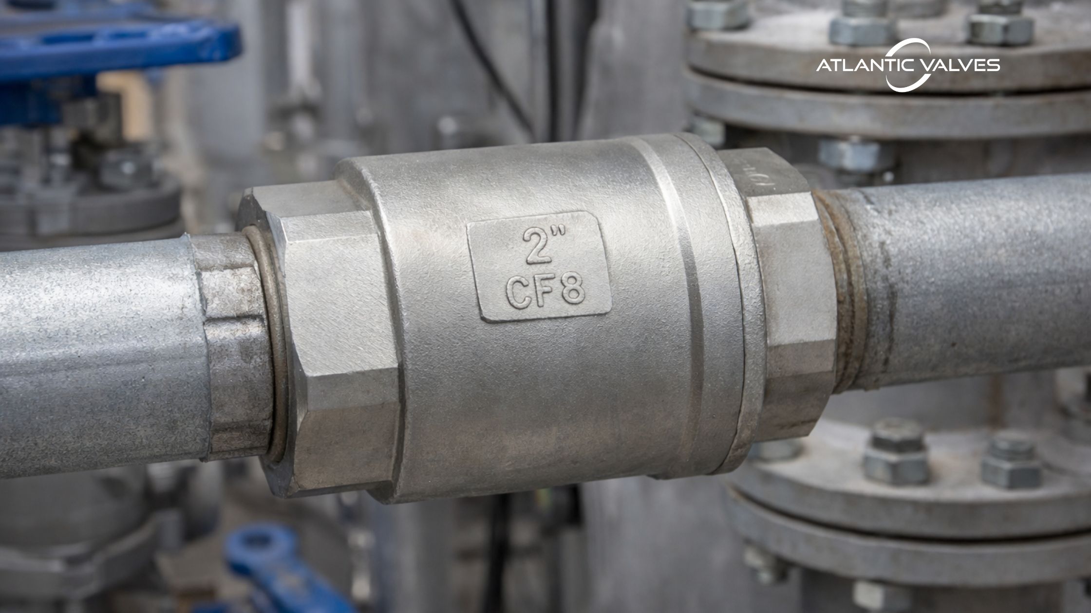
An inline check valve is a non-return device installed in a pipeline to prevent reverse flow. The closure element moves along the axis of the pipe and is usually spring-assisted. Opening and closing are controlled only by the pressure differential across the valve.
The valve opens when the upstream pressure exceeds the downstream pressure plus the spring force, moving the disc away from the seat and establishing flow. The valve is closed if the flow is decreased or when reverse flow starts reducing the pressure differential and causing the disc to be pushed back toward the seat. The response time depends on flow velocity, spring stiffness, and system pressure conditions.
What Makes An Inline Check Valve Different?
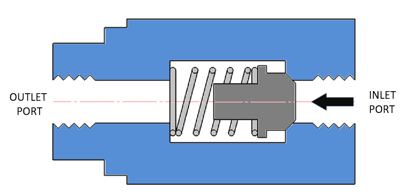
An inline Check Valve (often referred to as a spring-loaded or silent check valve) is designed so that the flow path remains coaxial with the pipeline. Unlike swing check valves, the disc or poppet moves along the flow axis and is most often assisted by a spring. This configuration offers:
- Compact design
- Reduced slamming potential
- Faster closing
- Suitable for vertical piping (upward flow)
The defining feature is the axial movement of the closure member. When forward differential pressure exceeds the cracking pressure, the disc lifts. When flow decays, the spring assists in closing before reverse flow establishes.
This axial geometry is what differentiates the inline Check Valve from traditional swing or tilting disc designs—and it is also what makes sizing more sensitive to flow velocity.
Sizing: Why Line Size Is Not Enough
One of the most common oversights in check valve selection is assuming that valve size = pipe size = correct performance.
Even if that works dimensionally. It doesn’t always work hydraulically.
Flow Velocity Considerations
An inline Check Valve requires enough velocity to fully open the disc. If velocity is too low:
- The disc may hover in a partially open position.
- Oscillation (chatter) can occur.
- Seat and guide wear accelerates.
As a rule of thumb, minimum flow velocity should often exceed 1.5–2.0 m/s for stable operation in water systems. However, the actual value depends on:
- Disc mass
- Spring constant
- Valve bore design
- Fluid density and viscosity
Distributors sometimes oversize check valves “for safety.” Ironically, oversizing reduces velocity and increases instability. Engineers should confirm:
Q=A×V
Where:
- Q = volumetric flow rate
- A = effective flow area
- V = velocity
The effective area inside an inline check valve may be smaller than the nominal pipe ID, so relying purely on pipe calculations can mislead selection.
Cv and Pressure Drop
Inline check valves typically have lower Cv than swing types due to:
- Spring obstruction
- Internal guide structure
- Narrower flow path
If pressure drop is critical (e.g., gravity-fed system), calculate:

Where:
- ΔP = Pressure Drop
- Q = volumetric flow rate
- Cv= effective flow area
A balanced selection targets:
- Fully open disc position at normal flow
- Acceptable ΔP under peak flow
- Stable closure at near-zero flow
In many industrial systems, a slightly smaller inline check valve with adequate velocity performs better than an oversized unit with marginal opening.
There’s always a balance between hydraulic efficiency and dynamic stability.
Cracking Pressure and System Dynamics
Cracking pressure is the minimum upstream pressure required to initiate disc lift. Typical spring-loaded inline check valves are available with cracking pressures ranging approximately from 0.1 bar to 1 bar, depending on spring preload and application requirements, based on common manufacturer offerings.
In pump discharge systems, cracking pressure contributes to total dynamic head. While often small, it may become significant in low-head centrifugal pumps.
Inline check valves are often selected in systems where transient behavior is a concern. Their spring-assisted closure reduces slam compared to swing check valves, but they are not immune to transient spikes if improperly sized.
Pressure Rating
When selecting pressure rating, engineers usually reference below standards:
- ASME Class (e.g., 150, 300)
- PN rating (e.g., PN16, PN25)
- JIS ratings (10K, 20K)
But pressure class alone is incomplete. Understanding the relationship between pressure and temperature is one of the integral skills in valve selection.
Always cross-check the body material, maximum operating temperature, and transient temperature excursions. In steam or hot oil lines, ignoring temperature derating leads to premature body distortion or seat leakage.
Flow Direction
Every check valve has a flow arrow. Installing against flow direction results in immediate blockage.
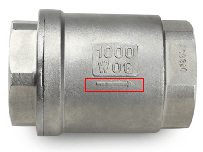
What is less obvious are the following installation nuances:
Vertical vs Horizontal Orientation
Inline check valve performance is affected not only by sizing and pressure rating, but also by installation orientation. Because most inline designs rely on axial disc movement and spring force for closure, gravity can either support or interfere with proper operation depending on flow direction. While manufacturers may provide specific allowances, general installation practices follow predictable mechanical behavior patterns, summarized below.
| Orientation | Suitability | Technical Remarks |
| Horizontal | Recommended | Standard installation configuration. Disc movement remains aligned with flow axis. |
| Vertical – Upward Flow | Recommended | Flow assists disc lift; gravity supports stable closing. Common in pump discharge risers. |
| Vertical – Downward Flow | Not Recommended
(unless specified) |
Gravity assists opening; reduced closing force; potential decrease in reverse sealing reliability. Manufacturer confirmation required. |
Pump Discharge Placement
Placement relative to pumps affects performance:
Recommended sequence:
Pump → Inline check valve → Isolation Valve
Positioning the inline check valve close to the pump discharge minimizes reverse column separation and reduces slam risk.
Long distances between pump and valve increase fluid inertia and transient magnitude.
Material Selection for Industrial Service
Material compatibility must align with:
- Fluid chemistry
- Temperature
- Abrasion level
- Pressure
Body Materials
Common body options include:
- Ductile iron (water systems)
- Carbon steel (general industrial)
- Stainless steel (corrosive media)
- Bronze or brass (smaller water lines)
For slurry or abrasive service, hardened seats or special alloys may be necessary. An inline check valve in a clean water system behaves very differently from one installed in a mining slurry pipeline.
Seat and Seal Materials
Seat leakage classification depends on seat material and surface finish.
Seal failure is one of the most common field issues. Distributors should confirm not just body material, but elastomer compatibility.
Performance Testing and Standards
Depending on project requirements, inline check valves may need compliance with:
- API 594 (check valves)
- MSS SP-125
- EN 12334
- ISO pressure testing standards
Hydrostatic testing ensures body integrity, but seat leakage testing verifies sealing performance. Engineers should request:
- Test certificates
- Material test reports (MTRs)
- Pressure test documentation
For critical systems, third-party inspection may be required.
Maintenance and Lifecycle Expectations
Inline check valves are generally low-maintenance, but not maintenance-free. Common field observations include spring failures, and seat wear due to debris.
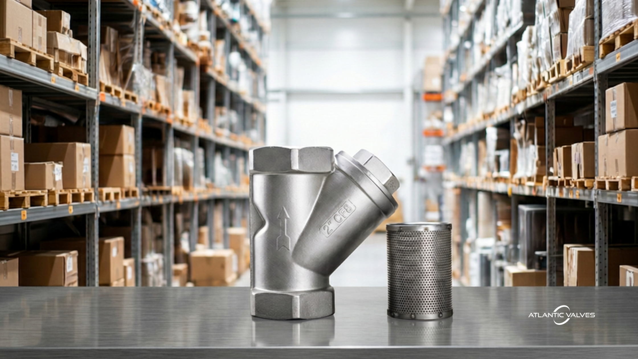
In systems without upstream filtration, debris can prevent full closure. Strainers may be recommended in sensitive applications.
Routine inspection intervals depend on the cycle frequency, fluid cleanliness and operating pressure.
Integrating Inline Check Valve Selection into System Design
Selection should not occur in isolation. It should be integrated with:
- Pump curve analysis
- System head calculations
- Surge modeling
- Maintenance strategy
For distributors, understanding the client’s application is essential. Asking the right questions helps avoid misapplication:
- What is the design flow rate?
- What is the minimum operating flow?
- What is the maximum operating pressure?
- Is the system prone to water hammer?
- What fluid is being handled?
A properly selected inline check valve contributes to system stability, protects pumps, and extends component life. A poorly selected one becomes a recurring maintenance issue.
Final Thoughts
Although they appear to be compact and straightforward on paper, an inline check valves’ real-world behavior is highly dependent on system dynamics.
For engineers, the focus should be on system dynamics and lifecycle reliability—not just nominal size. For distributors, understanding application details ensures proper recommendations and long-term customer satisfaction.
In practical terms, selecting the right inline check valve means balancing three core variables:
- Sizing based on actual flow conditions
- Pressure rating accounting for temperature and transients
- Correct installation respecting flow direction and orientation
Need stock support or help sourcing inline check valves for a customer requirement? Contact Atlantic Valves for fast response and product assistance.