Check valves are passive components with a very simple working mechanism: they open when flow moves forward and close when flow reverses. No power supply, no instrumentation, no complex control logic. And yet, when they fail, the consequences can be severe.
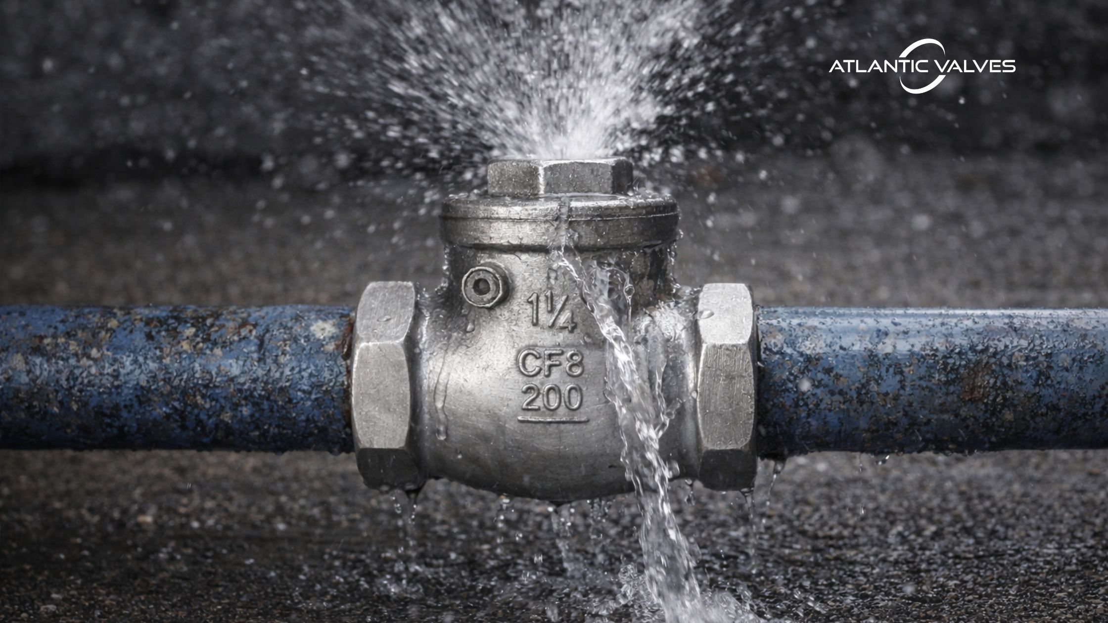
Backflow contamination. Pump damage. Water hammer. Flooded facilities. These are some of the consequences of a check valve failure. In industrial systems, a failed water line check valve is rarely an isolated issue — it’s usually the starting point of a chain reaction.
This is a walkthrough on all the most common water line check valve failures seen in industrial systems and, more importantly, explains how proper check valve selection prevents them
Why Do Water Line Check Valves Fail?
Check valves installed in industrial systems are operating in dynamic systems. This means that conditions where flow rates change, pumps start and stop, and pressure fluctuations travel through the piping are expected. When these situations occur, the check valve’s components, such as the disc, hinge, or spring, must react quickly. Instead of opening once and staying stable, the valve may repeatedly open and close, oscillate in the flow stream, or close suddenly during reverse flow. Over time, this repeated motion places mechanical stress on the valve internals and seating surfaces.
Because check valves interact directly with changing flow conditions, system dynamics play a major role in their reliability. When factors such as flow velocity, pump behavior, and potential transients are considered during valve selection, many common failures can be avoided.
Causes of Water Line Check Valve Failures
Water Hammer
The Failure Mechanism
During pump shutdown, forward velocity decays. If the disc does not close before flow reversal begins, reverse velocity accelerates the disc back toward the seat. The result is a slam; this rapid deceleration event produces a pressure spike.
The surge magnitude can exceed normal line pressure by multiples, especially in long discharge runs.
The Hydraulic Institute discusses these transient behaviors in pump system design guidance, emphasizing that check valve dynamic response directly affects surge magnitude. Hydraulic Institute Standards
Similarly, API 610 recommends that discharge check valves be selected to prevent reverse rotation and associated damage — implicitly acknowledging closure timing as critical.
| Root Cause | Prevention Strategy |
| Oversized swing check valves | Use spring-assisted or “silent” check valves for pump discharge |
| Low steady-state velocity | Avoid oversizing just to match the pipe size |
| Long vertical risers | Evaluate pump shutdown characteristics |
| High inertia systems | If possible, perform surge analysis in critical systems |
| No surge evaluation during design |
Swing check valves are gravity-assisted devices. In low-velocity water systems, they close late. And this delay is the whole problem.
In most industrial water systems, preventing slam is about choosing the right closing mechanism — not just the right size.
Disc Chattering Under Normal Flow/Oscillations
The Failure Mechanism
When flow velocity is insufficient to stabilize the disc in a fully open position, the disc oscillates. This creates:
- Seat fretting
- Hinge wear
- Fatigue on pins or springs
- Progressive sealing degradation
Root Cause
Oversizing is oftentimes the culprit.
A valve selected to match line size — instead of flow profile — may operate at 20–40% of ideal velocity. In those conditions, the disc never reaches a stable equilibrium.
Prevention Strategy
From a hydraulic standpoint, the valve must achieve stable full-open geometry at normal operating flow. That requires:
- Reviewing pump curve vs system curve
- Evaluating minimum continuous flow
For distributors especially, this is where application questions matter. “What’s the flow range?” is more important than “What’s the line size?”
Seat Leakage and Backflow
What Leakage Causes
- Pump reverse rotation
- Mechanical seal stress
- Increased restart torque
- Backflow contamination risk
| Root Cause | Prevention Strategy |
| Repeated slam events | Select resilient seats for clean water |
| Abrasive raw water | Avoid metal seating in particulate service |
| Misalignment | Confirm compatibility with disinfectants (chlorine exposure matters) |
| Incompatible elastomer selection | Prevent slam – because most seat damage begins here |
| Metal-to-metal seating in dirty service |
In centrifugal systems, reverse rotation after shutdown is specifically addressed in API 610, which emphasizes the discharge check valve function in preventing reverse flow.
For municipal or potable water applications, AWWA C508 provides design and material guidance to ensure reliable seating performance under waterworks conditions.
But even when a valve meets AWWA C508, performance still depends on correct hydraulic application.
Pressure Rating Misapplication
ASME B16.34 defines pressure-temperature ratings for valve bodies. These are based on steady-state conditions.
They are not surge allowances.
If transient pressure reaches 2–3× operating pressure during water hammer, the valve may exceed its allowable stress range even though “normal pressure” is within rating.
Field Consequences
- Body distortion
- Seat extrusion
- Flange leakage
- Bolt relaxation
Prevention Strategy
In water systems, consider:
- Maximum allowable working pressure
- Surge pressure envelope
- Pump trip transient modeling
If surge is unaccounted for, pressure class selection becomes guesswork.
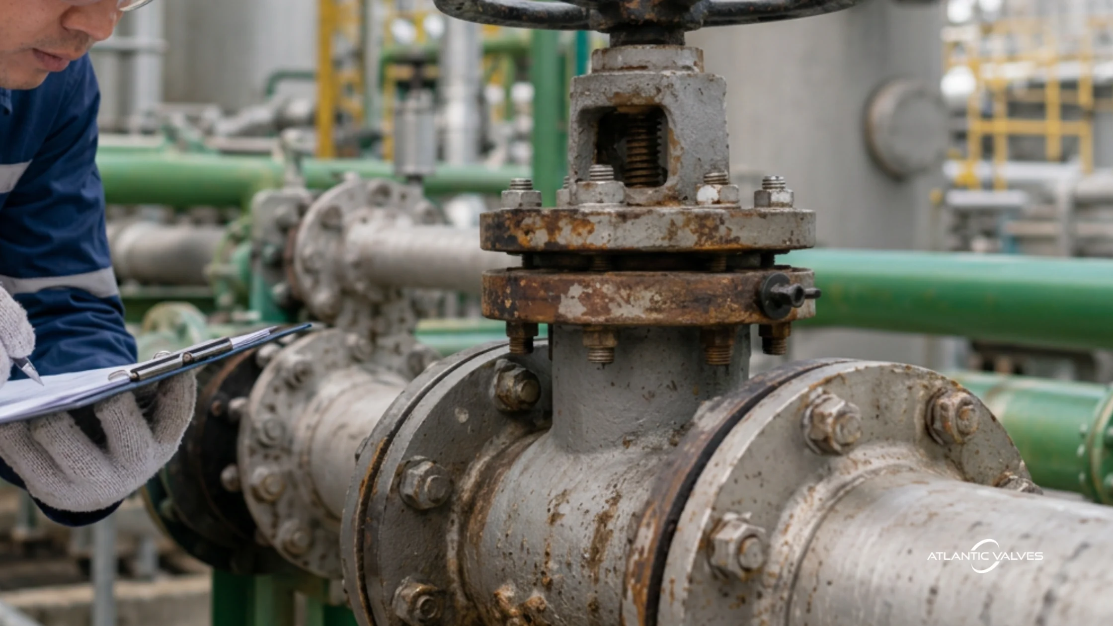
Corrosion and Material Degradation
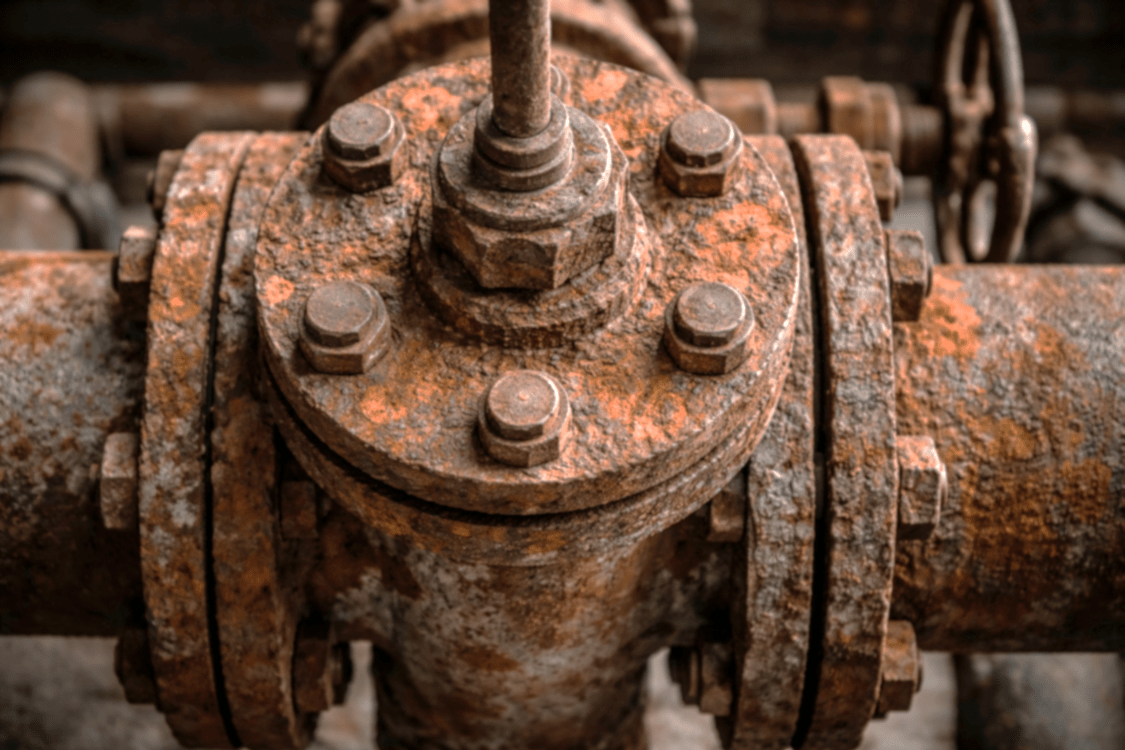
One of the causes of check valve failure is component damage due to material degradation caused by corrosion.
| Root Cause | Prevention Strategy |
| Chlorinated potable water | Epoxy-coated ductile iron body for buried lines |
| Coastal or marine air | 316 stainless for chlorinated or coastal exposure |
| Raw water with suspended solids | Bronze or specialty alloys for marine applications |
| Treated industrial cooling water | Confirm elastomer chemical compatibility |
Carbon steel internals in chlorinated systems degrade faster than many expect. Springs lose preload. Pins pit. Discs seize. Asking about water chemistry prevents premature replacement.
Installation Errors That Undermine Good Design
You can select the perfect valve — and still get failure.
Common examples:
- Swing check installed in vertical downward flow
- Insufficient straight run upstream
- Installed too close to the pump discharge nozzle
- Reversed orientation
Flow conditioning matters. Turbulence affects disc dynamics. Poor alignment accelerates wear.
A Real-World Scenario
Let’s say you have treated water running through a horizontal centrifugal pump with a 10” discharge line with a 65.6 ft vertical rise and frequently cycling.
A basic swing check technically satisfies pipe size and pressure class. However, the engineering review shows a large moving column of water due to the vertical rise and varying flow due to frequent cycling. These conditions mean the water momentum is high, which can cause problems when the valve closes.
In this case, a spring-assisted axial flow check valve that is properly sized for the operating velocity can perform much better. It closes faster and more smoothly, which helps reduce pressure surges, limits disc impact during closure, and minimizes wear on the valve seat.
The initial cost of this valve is slightly higher than that of a basic swing check. But over time, the reduction in water hammer, maintenance, and component wear typically leads to a much lower lifecycle cost.
Final Thoughts
Most water line check valve failures are mechanical responses to hydraulic conditions that were either underestimated or not evaluated. Water hammer, disc chatter, leakage, corrosion, pump backspin, and fouling often trace back to the same underlying issues: oversizing, incorrect valve type, mismatched materials, or failure to account for system dynamics such as pump cycling and surge conditions.
This is why proper selection matters so much. A check valve should not be chosen based on pipe size alone. Flow profile, velocity range, water quality, installation orientation, and shutdown behavior all influence how the valve will actually perform in service. When these factors are considered early in the design or procurement process, many of the common failure modes simply never appear.
Need Help Selecting a Check Valve?
Atlantic Valves supports distributors, OEMs, and engineers with stocked industrial check valves and application guidance. If you are specifying valves for water systems, we can help you choose the correct design for long-term reliability.