The orifice size of a valve affects its performance in a fluid system, influencing flow rates and flow characteristics. Valve distributors should understand how to calculate valve orifice sizes. It is a critical technical skill that significantly improves your competitive advantage. Understanding correct orifice sizing prevents product failures and reduces the frequency of product returns, thus enhancing customer trust. It also enables you to offer tailored flow control solutions to new customers, building and boosting long-term customer loyalty.
This guide provides a step-by-step approach for calculating orifice sizes of valves and explains why it is important for distributors to master this skill.
Technical Breakdown
- Orifice sizes affect fluid velocity, pressure drop, turbulence, and choked flow onset.
- Too small orifice → excessively high velocity → cavitation, erosion , seat damage, overheating.
- Too large orifice → unstable control, hunting, water hammer, poor accuracy.
- Steam can enter sonic choking (flow will not increase even if pressure increases.)
- Orifice directly determines Cv behavior, flow linearity, coil heating, and erosion link.
Small holes can make the fluid move too fast and damage the valve, Big holes make the valve unstable. The goal is the correct size.
Why Distributors Must Understand Orifice Size Calculations
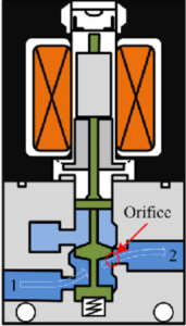
The orifice is the opening through which fluids flow once a valve is actuated. The orifice size impacts both the functionality and reliability of a valve. It implies that valve distributors require adequate knowledge to interpret system flow requirements and recommend the appropriate products to customers, some of whom may have little or no knowledge of orifice sizes. Mastering orifice size calculations enables distributors to:
- Accurately recommend valves – You can easily interpret system flow requirements and recommend valves with correct orifice sizes. A valve with an orifice that is too small causes the system to starve for flow, becomes susceptible to overheats (for automated valves) and premature actuator failures. An oversized orifice, on the other hand, exhibits poor control accuracy and is unstable, frequently subjecting the fluid system to shock loads.
- Reduce returns and warranty issues – improper valve sizing is one of the leading causes of product returns. Understanding orifice sizing reduces RMAs, meaning you focus more on new customer acquisitions rather than replacing products and refunding customers.
- Improve buyer confidence and trust – customers prefer distributors that can explain valve performances based on orifice-flow correlations instead of generic product descriptions.
- Customize flow control solutions – distributors who understand orifice sizing can effectively offer custom flow control solutions to meet system-specific constraints. Such constraints may require the integration of different products, and understanding how to size each valve reduces mismatches.
Think of the orifice as the valve’s throat:
- Too small → choking
- Too big → unstable
- Correct orifice = correct flow. Wrong orifice = problems.
Procedure for Calculating Orifice Sizes
Calculating orifice sizes involves applying fluid flow dynamics to determine if the internal valve opening (diameter) can achieve desired flow rates at a specific pressure drop. Here is a simple step-by-step procedure you can use to calculate orifice sizes and verify if Atlantic Valves products in your inventory can meet the customer’s requirements.
- Collect application-specific data – gather information about the intended application of the valve from the customer. This includes the type of fluid media, desired flow rate, inlet and outlet pressure, fluid temperature range and viscosity/specific gravity of service fluids.
- Determine the flow coefficient (Cv). Use the formula for Cv, which is:
Cv=Q√(SG/ΔP)
Q- Discharge in gallons per minute (GPM)
SG- specific gravity
ΔP- pressure drop in PSI
You can skip this step if the customer already knows Cv and wants to work with a specific value.
- Convert Cv to orifice diameter. You can use two methods for this.
- Using the empirical formula for quickly approximating the internal diameter of a solenoid, ball or general-purpose control valve. The formula is expressed as:
Cv=25*d2
Cv- flow coefficient
d – orifice diameter (in inches)
-
-
- Flow equation using area and flow mechanics
-
Cv≈29.9*Cd*A
Cv – flow coefficient
29.9 – fluid mechanics constant
Cd – discharge coefficient (Manufacturers use an approximate value of 0.62-0.70 for orifices with sharp edges and 0.75-0.82 for rounded edges)
A – area (𝜋d2/4)
To find the diameter of the orifice using the formula, substitute A with the formula for the area of a circle.
Cv=29.9*Cd*(𝜋d2/4)
Solving for d yields:
d=√(4Cv/(29.9*Cd*𝜋))
Technical Notes
-
- Sharp edged orifice follows the 25*d2 rule.
- Cd depends on geometry, sharp edge: 0.62-0.70, rounded: 0.75-0.82.
- Very small orifices (<2mm) behave differently due to laminar flow.
- Validate orifice sizes against the manufacturer’s chart. Use the calculated orifice size figures to select the appropriate valve. Use the manufacturer’s product manuals to verify whether the selected product meets the pressure and flow fluctuation requirements of the fluid system.
Note: Even if your calculated diameter is correct, always cross check with:
-
- Flow curves
- Pressure drop charts
- Cavitation limits
- Actual valve Cv values
- Pressure temperature ratings
Theoretical values are not always equal to real test results. Manufacturer charts capture internal geometry, losses, and real performance.
- Consider safety and special operating conditions. Check if the fluid system has any special operating conditions such as:
- Liquids – Cavitation and flashing risks (Hot liquids may require anti-flashing consideration)
- Gas – Choked flow must be checked (Gas may reach sonic flow at the orifice)
- Steam – density swings require safety margins (Steam heats valve bodies , coil derating may be required)
Some fluids act differently and may need special sizing rules.
Practical Examples
To understand orifice sizing better, let us use practical examples, each covering the above formulas.
Case 1: A customer wants to buy a solenoid valve for an industrial steam supply line. They estimate that the desired flow coefficient is 4.5. Which solenoid valve from Atlantic Valves will you recommend?
Using the formula Cv=25*d2
4.5=25*d2
d2=4.5/25 =0.18
d=√0.18 = 0.4242 in (10.78mm)
Note: Steam valves typically offer larger orifices than the minimum required to give:
- Better response time
- Less sensitivity to SG changes (steam directly fluctuates, 40-60%)
- Lower velocity through the orifice (reduces erosion and noise)
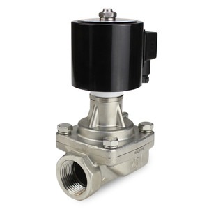
The approximate orifice size is 0.42 inch. The most appropriate valve you can recommend based on this calculation is a ½” Stainless Steel Steam Solenoid Valve (SKU: SRS-15). The valve has a Cv of 4.8 and an orifice diameter of 15mm, providing a safety factor to account for pressure and temperature changes in the steam pipeline.
½” Stainless Steel Steam Solenoid Valve (SKU: SRS-15)
Case 2: Another customer wants a water service valve. In their design, they expect a pressure drop of 5 PSI and a flow rate of 40 GPM. Which manual ball valve is recommended for this customer?
First, calculate the Cv of the valve. Since it is for water service, the specific gravity is 1
Cv=Q√(SG/ΔP)
Cv=40√(⅕)
Cv=17.88
Next, use the formula for estimating orifice size.
Cv=25*d2
17.88=25*d2
d=√(17.88/25)= 0.846 (21.48mm)
Based on this calculation, you can recommend a 1”, 2-Piece Stainless Steel Manual Ball Valve (SKU: BV-2PC-2025-S). It is the next standard valve in the inventory.
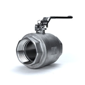
1”, 2-Piece Stainless Steel Manual Ball Valve (SKU: BV-2PC-2025-S)
Inventory Lookup Tip: Search your inventory for valves whose Cv is equal or greater than the manually calculated value. In cases where only nominal orifice sizes are listed, use the calculated orifice diameter as a filter. From the above examples, you offer a valve whose orifice size is slightly bigger than the calculated values.
Using Orifice Size Calculations to Improve Sales
As mentioned, knowing how to calculate orifice sizes is a skill that goes beyond simple stock identification. It can help distributors to build their business and improve sales. Here is how:
- Building quick-sizing templates for sales teams – you can leverage the valve sizing information to create quick, easy-to-use Excel and Google Sheet templates for your sales teams. This helps them to size valves on the go, based on the information they collect from customers. The quick-sizing templates help sales teams to narrow down on products, while ensuring they recommend valves with the right orifice sizes.
- Reduce lead times – distributors who understand how to calculate orifice sizes can maintain lean inventories. Calculating orifice sizes helps you identify the most demanded valves and flow ranges. You also know which orifice sizes are suitable for which applications. With this knowledge, you can quickly and accurately process customer orders.
- Improve training for technical staff – utilize the information for calculating orifice sizes to train staff on the fundamentals of valve sizing. Staff who understand orifice logic are more likely to win B2B deals and maintain customer bases.
- Create pre-configured product bundles – by calculating orifice sizes, you can create an in-house product bundle with pre-configured orifice sizing. For example, you can segregate inventory such that you have a section for high-flow solenoid valves (¼”-½”) and another for large orifice valves ( more than 1” orifice size). Pre-configured product bundles make it easier for sales teams with less knowledge of orifice sizes to pick and process customer orders.
Final Words
If you are an Atlantic Valves distributor or planning to join us, it is important for you to learn how to calculate valve orifice size. Learn how to calculate and match orifice sizes to different fluid applications. You can create in-house quick calculation templates to further empower your sales teams and ensure they can communicate orifice-dependent flow characteristics to customers. Consult our technical teams if you face difficulty calculating orifice sizes.